Dogs Repellent System
Introduction
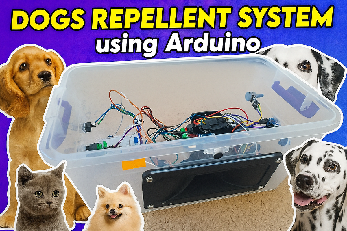
I live in an area crowded with stray dogs and wild animals. Almost every night, the constant barking of dogs caused me severe headaches, stress, and sleeplessness. I wanted to find a humane way to repel dogs and keep animals away from my home without harming them.
I reviewed many commercial devices available online, but most of them were ineffective. Their range was extremely limited (often less than 5 meters) and they lacked real control over frequency, intensity, or operating modes.
This motivated me to design and build my own ultrasonic animal repellent device. My system achieves a range of 15–20 meters and provides full control over sound intensity, sharpness, and tone variations.
As we know, humans can generally hear sounds between 20 Hz and 20 kHz. However, many animals—especially dogs—can hear ultrasonic frequencies well above 20 kHz. This difference in hearing range forms the basis of the project: creating ultrasonic waves that are uncomfortable for animals but inaudible to humans.
The working principle is straightforward:
- The Arduino microcontroller generates ultrasonic signals.
- The amplifier module boosts the signals to sufficient power.
- The high-performance piezo tweeter outputs the sound across ultrasonic ranges.
The result is a reliable and efficient device capable of repelling animals without causing harm.
Features
- Adjustable ultrasonic frequency output via potentiometer.
- Multiple operating modes (tone, sharpness, modulation) using three push buttons.
- Automatic activation when barking is detected using the sound sensor.
- High-power amplifier with ultrasonic frequency support.
- Optional cooling system for long-term use.
- Effective range of 15–20 meters, far greater than typical commercial products.
Parts List
- Arduino Uno
- Serves as the main controller of the system.
- Generates ultrasonic waveforms with adjustable frequency.
- Amplifier Module (XH-M190 TPA3116D2 2×100W)
- Chipset: TPA3116
- Type: Two-channel stereo amplifier
- Output Power: 2 × 100W
- Input Impedance: 51k × 2
- Output Load: 4–8 Ω
- Frequency Response: 14–100 kHz (supports ultrasonic frequencies, making it ideal for this project)
- Supply Voltage: DC 12–24V
- Note: Other amplifiers may be used, but the frequency response range must be verified to ensure they handle ultrasonic frequencies.
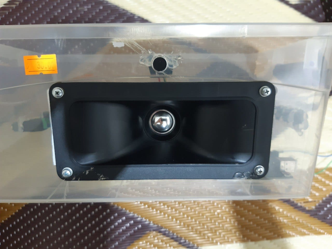
- High-Frequency Piezo Tweeter (Kemo L001)
- German-made, designed for ultrasonic applications.
- Standard speakers cannot produce ultrasonic output effectively, so using a specialized tweeter is critical.
- Potentiometer (10k)
- Controls the output frequency of the Arduino’s generated signal.
- Allows dynamic adjustment for different repelling effects.
- Push Buttons (×3)
- Control different operating modes:
- Mode 1: Continuous ultrasonic emission
- Mode 2: Variable sharpness of the signal
- Mode 3: Frequency modulation with different notes for improved effectiveness against dogs
- Control different operating modes:
- LED Indicators (Red & Blue)
- Indicate device status and operating mode.
- Connected with resistors (330 Ω or 1 kΩ). Lower resistance = brighter LED.
- Sound Sensor Module
- Detects barking or external noise.
- Prevents the system from running continuously, which saves energy and reduces amplifier heating.
- Automatically triggers the ultrasonic emission only when barking is detected.
- Cooling Fan (24V, Optional)
- Provides airflow to cool down the amplifier.
- Strongly recommended when running the amplifier at maximum power for long durations.
- DC-DC Step-Down Converter (12–24V to 5V)
- Powers the Arduino and other low-voltage sensors.
- Ensures stable 5V supply even when using a high-voltage 24V input.
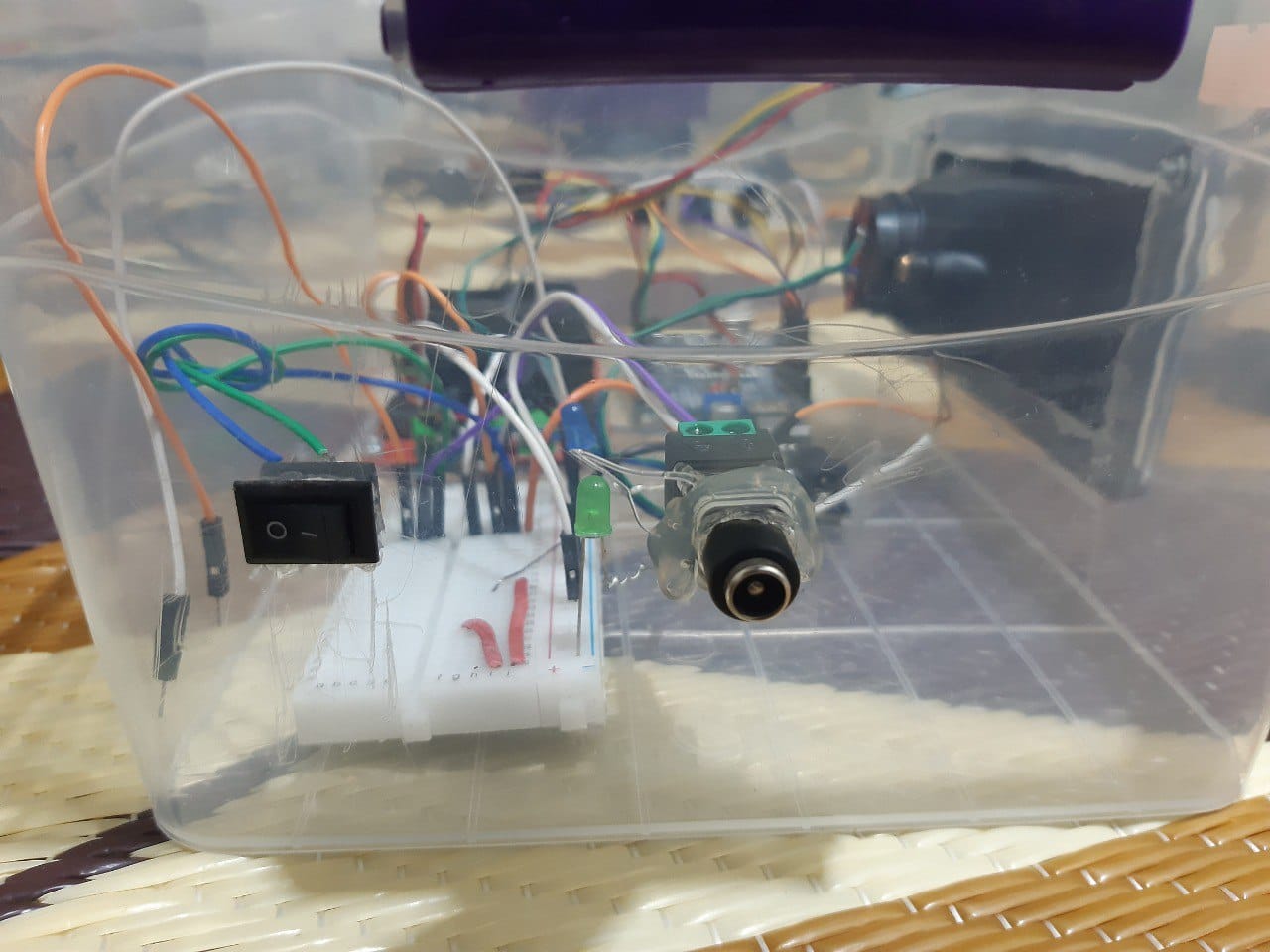
- Power Switch & DC Power Jack (12–24V Input)
- Allows turning the device on/off easily.
- Compatible with a wide range of power adapters.
Technical Operation
The ultrasonic repellent system is built around an Arduino Uno, which is responsible for generating the ultrasonic signals. Using hardware timers and the tone() function, the Arduino produces square waves at frequencies between 29 kHz and 45 kHz, a range well above the human hearing threshold but clearly audible to dogs and many other animals. The exact step size of the frequency sweep is controlled by a 10k potentiometer connected to an analog input. Turning the knob adjusts how quickly the signal moves from one frequency to another, making the sound more or less irritating to animals.
The device offers three operating modes, each activated by a dedicated push button. Mode 1 sweeps the frequency between 29 and 35 kHz, Mode 2 between 35 and 43 kHz, and Mode 3 between 40 and 45 kHz. By shifting across different ultrasonic bands, the system ensures that animals cannot easily adapt to a single tone. When a button is pressed, the selected mode runs for ten seconds, with the green LED indicating active operation. If no mode is active, the blue LED blinks to show the device is in standby.
In addition to manual activation, the system also responds automatically to sound. A microphone module continuously monitors the environment, and when barking exceeds a defined threshold, the Arduino activates one of the modes for thirty seconds. This automatic triggering makes the device more practical, since it only operates when unwanted noise is detected.
Because the Arduino’s output alone is too weak to drive a speaker, the signal is amplified by the TPA3116D2 stereo amplifier, which is capable of delivering up to 100 watts per channel and supports frequencies as high as 100 kHz. The amplified signal is sent to a Kemo L001 high-frequency piezo tweeter, which efficiently converts it into ultrasonic sound. The acoustic output can cover a distance of 15 to 20 meters.
The system is powered by a 12–24 V DC supply. A step-down converter provides the 5 V needed for the Arduino and sensors, while the amplifier runs directly from the higher supply voltage. At high power the amplifier generates significant heat, so a 24 V cooling fan is added to maintain stable operation during extended use.
Wiring Diagram
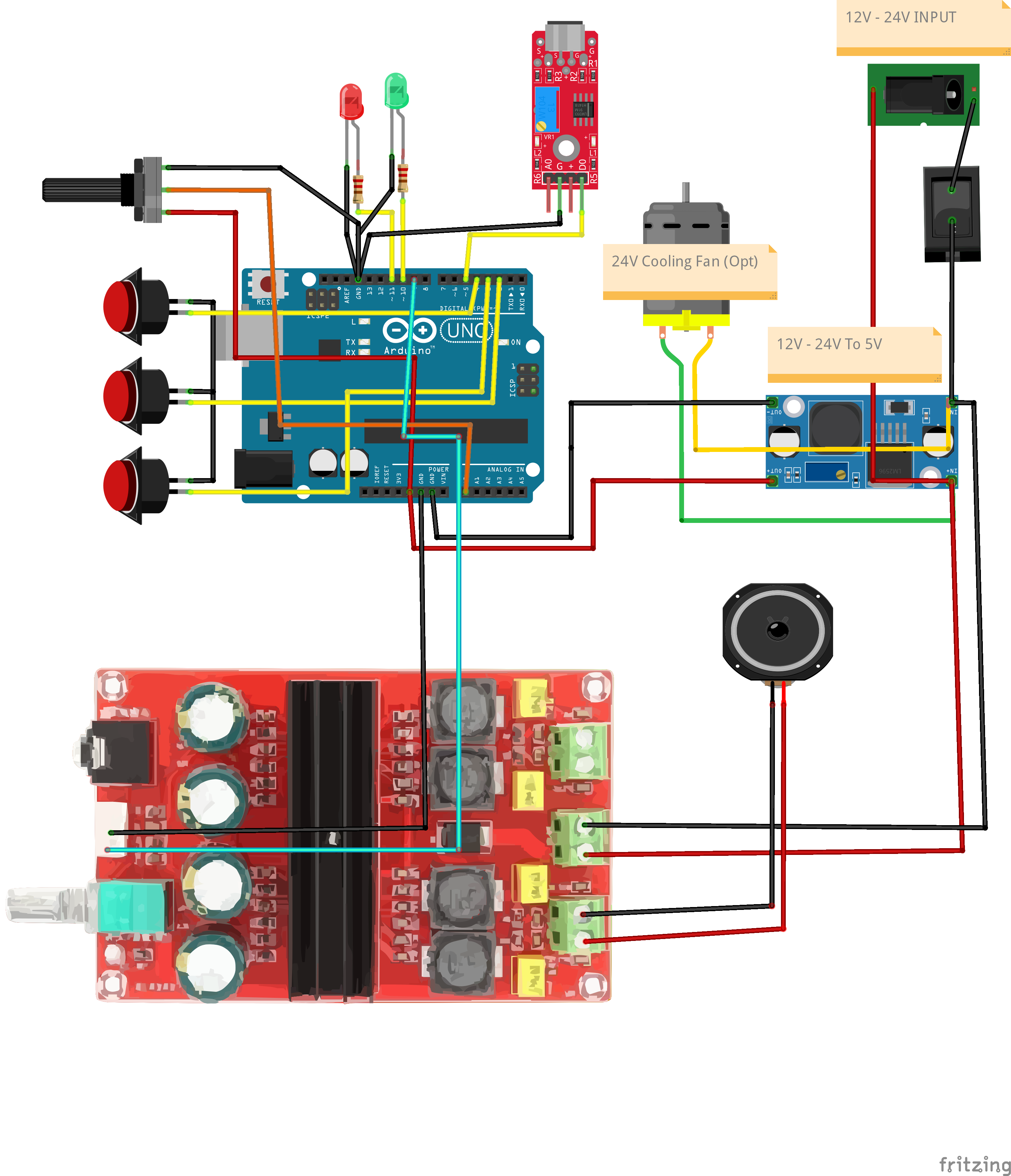
Below is the wiring schematic created in Fritzing, showing how each component is connected:
Code
Pin and Variable Setup
const int OUT_PIN = 5;
const int SAMPLE_TIME = 10;
unsigned long millisCurrent;
unsigned long millisLast = 0;
unsigned long millisElapsed = 0;
int sampleBufferValue = 0;
int currentMode = 0;
bool modeActive = false;
unsigned long modeActivationTime = 0;OUT_PINis used for sampling sound input.- Timing variables (
millisCurrent,millisLast, etc.) help measure elapsed time without blocking code. currentModestores the currently selected ultrasonic mode (1, 2, or 3).modeActiveandmodeActivationTimeare used to keep track of whether a mode is active and for how long.
LED and Button Configuration
const int Green_Led = 10;
const int Blue_Led = 11;
const int Mode_1_Button = 2;
const int Mode_2_Button = 3;
const int Mode_3_Button = 4;- Green LED indicates active ultrasonic emission.
- Blue LED indicates standby or blinking mode.
- Three buttons are connected to digital pins 2, 3, and 4, each selecting a different frequency range.
Sound Detection Parameters
const int Sound_Limit = 180;  // Bark sensitivity
const int Mode_1_Limits[2] = { 29000, 35000 };
const int Mode_2_Limits[2] = { 35000, 43000 };
const int Mode_3_Limits[2] = { 40000, 45000 };Sound_Limitdetermines how sensitive the system is to barking or external noise. Increasing this value makes it less sensitive.- each button selects a frequency sweep mode across a specific ultrasonic band:
- Mode 1 (Button 1): Sweeps between 29–35 kHz.
- Mode 2 (Button 2): Sweeps between 35–43 kHz.
- Mode 3 (Button 3): Sweeps between 40–45 kHz.
Setup Function
void setup() {
  pinMode(Mode_1_Button, INPUT_PULLUP);
  pinMode(Mode_2_Button, INPUT_PULLUP);
  pinMode(Mode_3_Button, INPUT_PULLUP);
  pinMode(Green_Led, OUTPUT);
  pinMode(Blue_Led, OUTPUT);
  digitalWrite(Blue_Led, HIGH);  // Off initially
}- Buttons use INPUT_PULLUP, meaning they are normally HIGH and become LOW when pressed.
- LEDs are set as outputs.
- Blue LED starts in the OFF state.
Main Loop
void loop() {
  millisCurrent = millis();
  millisElapsed = millisCurrent - millisLast;

  if (digitalRead(OUT_PIN) == LOW) {
    sampleBufferValue++;
  }

  if (millisElapsed > SAMPLE_TIME) {
    sampleBufferValue = 0;
    millisLast = millisCurrent;
  }

  if (sampleBufferValue > Sound_Limit) {
    activateMode(30);  // Bark detected → 30 seconds active
  } else {
    if (digitalRead(Mode_1_Button) == LOW && currentMode != 1) {
      currentMode = 1;
      activateMode(10);
    } else if (digitalRead(Mode_2_Button) == LOW && currentMode != 2) {
      currentMode = 2;
      activateMode(10);
    } else if (digitalRead(Mode_3_Button) == LOW && currentMode != 3) {
      currentMode = 3;
      activateMode(10);
    }
  }
  if (currentMode == 0) {
    blinkBlueLed();
  }
}- If barking is detected (
sampleBufferValue > Sound_Limit), the device activates for 30 seconds. - If no barking is detected, pressing one of the buttons activates the corresponding mode for 10 seconds.
- If no mode is active, the blue LED blinks every 0.5 seconds to show standby.
Mode Activation
void activateMode(unsigned long duration) {
  modeActive = true;
  modeActivationTime = millisCurrent;
  digitalWrite(Blue_Led, LOW);
  digitalWrite(Green_Led, HIGH);

  while (modeActive) {
    if (millisCurrent - modeActivationTime >= duration * 1000) {
      modeActive = false;
      noTone(9);
      digitalWrite(Blue_Led, HIGH);
      digitalWrite(Green_Led, LOW);
    } else {
      switch (currentMode) {
        case 1: Mode_1(); break;
        case 2: Mode_2(); break;
        case 3: Mode_3(); break;
      }
    }
    millisCurrent = millis();
  }
}- Turns the green LED ON and blue LED OFF during operation.
- Keeps the chosen mode active for the selected duration (10 or 30 seconds).
- When time expires, the tone stops and LEDs reset.
Mode Implementations
Each mode sweeps through its frequency range using the potentiometer to set the step size.
void Mode_1() {
  unsigned int Jumping_Value = map(analogRead(A0), 0, 1023, 100, 1000);
  for (unsigned int x = Mode_1_Limits[0]; x <= Mode_1_Limits[1]; x += Jumping_Value) {
    tone(9, x);
  }
  for (unsigned int x = Mode_1_Limits[1]; x >= Mode_1_Limits[0]; x -= Jumping_Value) {
    tone(9, x);
  }
}- Mode 1 sweeps between 29 kHz and 35 kHz.
- Step size depends on potentiometer reading.
- The same logic applies to Modes 2 and 3 with their respective frequency ranges.
The potentiometer sets the sweep step size, meaning it controls how “smooth” or “aggressive” the frequency changes are. This prevents dogs from adapting to a single fixed tone. The green LED lights up while a mode is active, and the blue LED blinks when the system is idle.
Full Code
const int OUT_PIN = 5;
const int SAMPLE_TIME = 10;
unsigned long millisCurrent;
unsigned long millisLast = 0;
unsigned long millisElapsed = 0;
int sampleBufferValue = 0;
int currentMode = 0;
bool modeActive = false;
unsigned long modeActivationTime = 0;
const int Green_Led = 10;  // Green LED pin
const int Blue_Led = 11;   // Blue LED pin
const int Mode_1_Button = 2;
const int Mode_2_Button = 3;
const int Mode_3_Button = 4;
const int Sound_Limit = 180;                    //increse it if you want it to detect only louder sounds
const int Mode_1_Limits[2] = { 29000, 35000 };  // mode 1 frequency range {from , to}
const int Mode_2_Limits[2] = { 35000, 43000 };  // mode 2 frequency range {from , to}
const int Mode_3_Limits[2] = { 40000, 45000 };  // mode 3 frequency range {from , to}
unsigned int Jumping_Value;                     // The counting Steps

void setup() {
  // Serial.begin(9600);
  pinMode(Mode_1_Button, INPUT_PULLUP);
  pinMode(Mode_2_Button, INPUT_PULLUP);
  pinMode(Mode_3_Button, INPUT_PULLUP);
  pinMode(Green_Led, OUTPUT);    // Set Green LED pin as OUTPUT
  pinMode(Blue_Led, OUTPUT);     // Set Blue LED pin as OUTPUT
  digitalWrite(Blue_Led, HIGH);  // Turn off Blue LED initially
}

void loop() {
  millisCurrent = millis();
  millisElapsed = millisCurrent - millisLast;

  if (digitalRead(OUT_PIN) == LOW) {
    sampleBufferValue++;
  }

  if (millisElapsed > SAMPLE_TIME) {
    sampleBufferValue = 0;
    millisLast = millisCurrent;
  }

  if (sampleBufferValue > Sound_Limit) {
    // Activate the mode for 30 seconds
    activateMode(30);
  } else {
    // Check for button presses and activate the mode for 10 seconds
    if (digitalRead(Mode_1_Button) == LOW && currentMode != 1) {
      currentMode = 1;
      activateMode(10);
    } else if (digitalRead(Mode_2_Button) == LOW && currentMode != 2) {
      currentMode = 2;
      activateMode(10);
    } else if (digitalRead(Mode_3_Button) == LOW && currentMode != 3) {
      currentMode = 3;
      activateMode(10);
    }
  }
  if (currentMode == 0) {
    blinkBlueLed();
  }
}

void blinkBlueLed() {
  static unsigned long lastBlinkTime = 0;
  static bool blueLedState = LOW;

  if (millis() - lastBlinkTime >= 500) {  // Blink every 500ms (half a second)
    blueLedState = !blueLedState;         // Toggle the LED state
    digitalWrite(Blue_Led, blueLedState);
    lastBlinkTime = millis();
  }
}
void activateMode(unsigned long duration) {
  modeActive = true;
  modeActivationTime = millisCurrent;
  digitalWrite(Blue_Led, LOW);    // Turn on Blue LED
  digitalWrite(Green_Led, HIGH);  // Turn on Green LED

  while (modeActive) {
    // Check if the mode should stay active for the specified duration
    if (millisCurrent - modeActivationTime >= duration * 1000) {
      modeActive = false;
      noTone(9);                     // Turn off the tone when the mode deactivates
      digitalWrite(Blue_Led, HIGH);  // Turn off Blue LED
      digitalWrite(Green_Led, LOW);  // Turn off Green LED
    } else {
      // Keep the mode active here, depending on the currentMode
      switch (currentMode) {
        case 1:
          Mode_1();
          break;
        case 2:
          Mode_2();
          break;
        case 3:
          Mode_3();
          break;
      }
    }
    millisCurrent = millis();
  }
}

void Mode_1() {
  unsigned int Jumping_Value = map(analogRead(A0), 0, 1023, 100, 1000);
  for (unsigned int x = Mode_1_Limits[0]; x <= Mode_1_Limits[1]; x += Jumping_Value) {
    // Serial.print("Mode 1: ");
    // Serial.println(x);
    tone(9, x);
  }
  for (unsigned int x = Mode_1_Limits[1]; x >= Mode_1_Limits[0]; x -= Jumping_Value) {
    // Serial.print("Mode 1: ");
    // Serial.println(x);
    tone(9, x);
  }
}

void Mode_2() {
  unsigned int Jumping_Value = map(analogRead(A0), 0, 1023, 100, 1000);
  for (unsigned int y = Mode_2_Limits[0]; y <= Mode_2_Limits[1]; y += Jumping_Value) {
    // Serial.print("Mode 2: ");
    // Serial.println(y);
    tone(9, y);
  }
  for (unsigned int y = Mode_2_Limits[1]; y >= Mode_1_Limits[0]; y -= Jumping_Value) {
    // Serial.print("Mode 2: ");
    // Serial.println(y);
    tone(9, y);
  }
}

void Mode_3() {
  unsigned int Jumping_Value = map(analogRead(A0), 0, 1023, 100, 1000);
  for (unsigned int z = Mode_3_Limits[0]; z <= Mode_3_Limits[1]; z += Jumping_Value) {
    // Serial.print("Mode 3: ");
    // Serial.println(z);
    tone(9, z);
  }
  for (unsigned int z = Mode_3_Limits[1]; z >= Mode_3_Limits[0]; z -= Jumping_Value) {
    // Serial.print("Mode 3: ");
    // Serial.println(z);
    tone(9, z);
  }
}
Test and Results
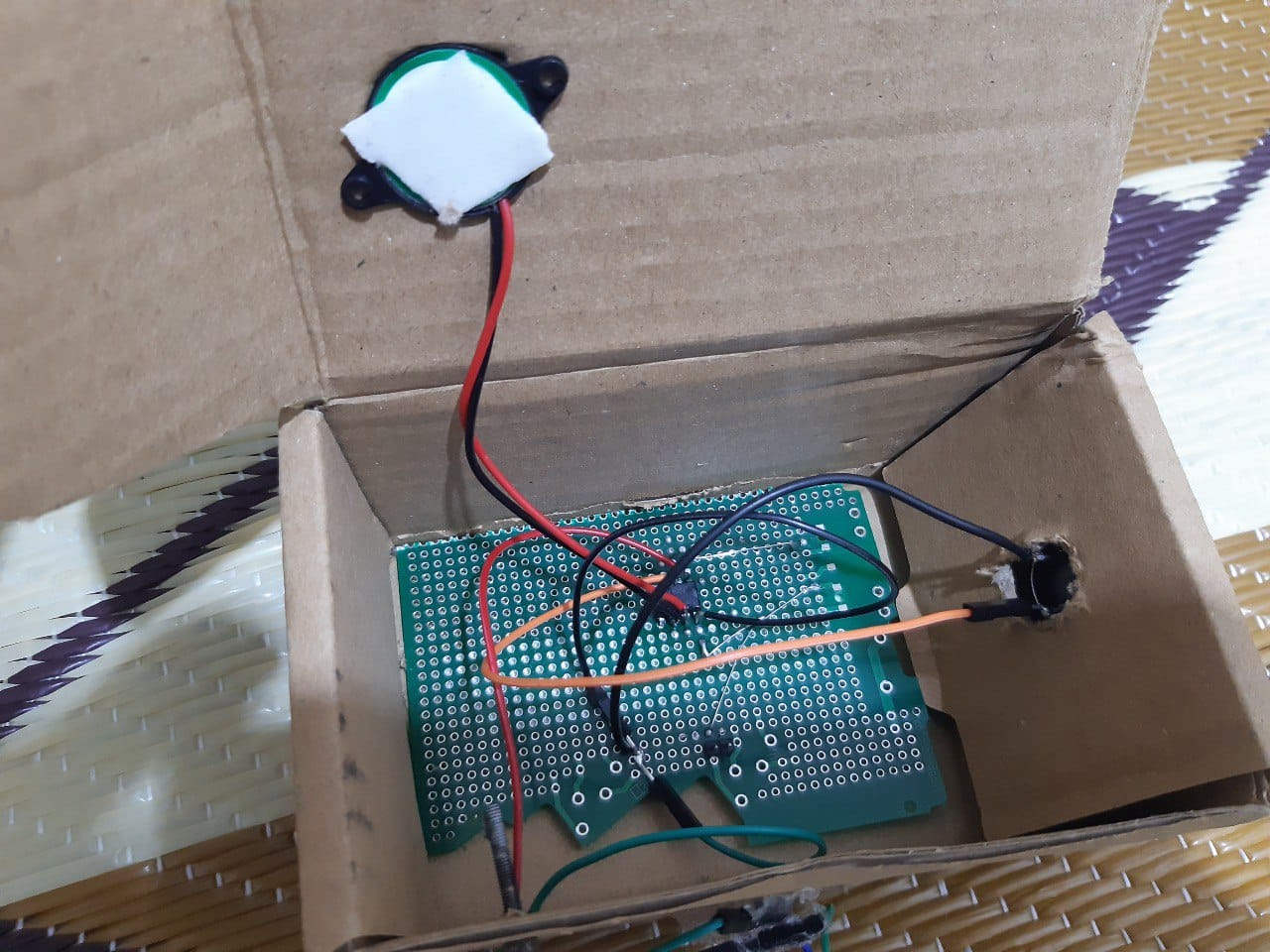
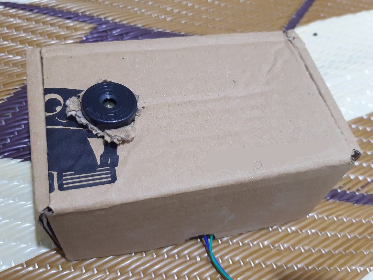
To confirm that the ultrasonic frequencies generated by my device were actually present, I used a simple bat detector circuit based on the PicoBat project. This circuit is shown in the image below:
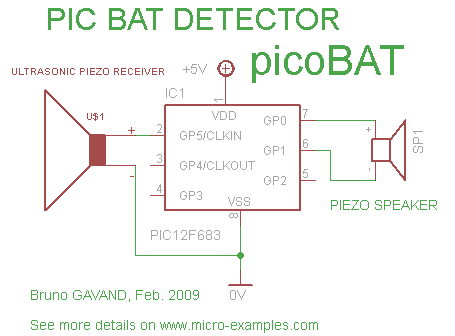
The idea of this circuit is to "hack" the PIC oscillator by replacing its crystal with an ultrasonic piezo sensor. In this configuration, the oscillator frequency depends directly on incoming ultrasonic waves. The PIC then divides this frequency by four and outputs it through a piezo speaker, making the originally inaudible ultrasonic signals clearly audible.
- The ultrasonic piezo receiver acts as the input sensor in place of the crystal/resistor.
- The PIC12F683 performs the oscillation and frequency division.
- The piezo speaker (SP1) outputs the shifted-down signal as an audible tone.
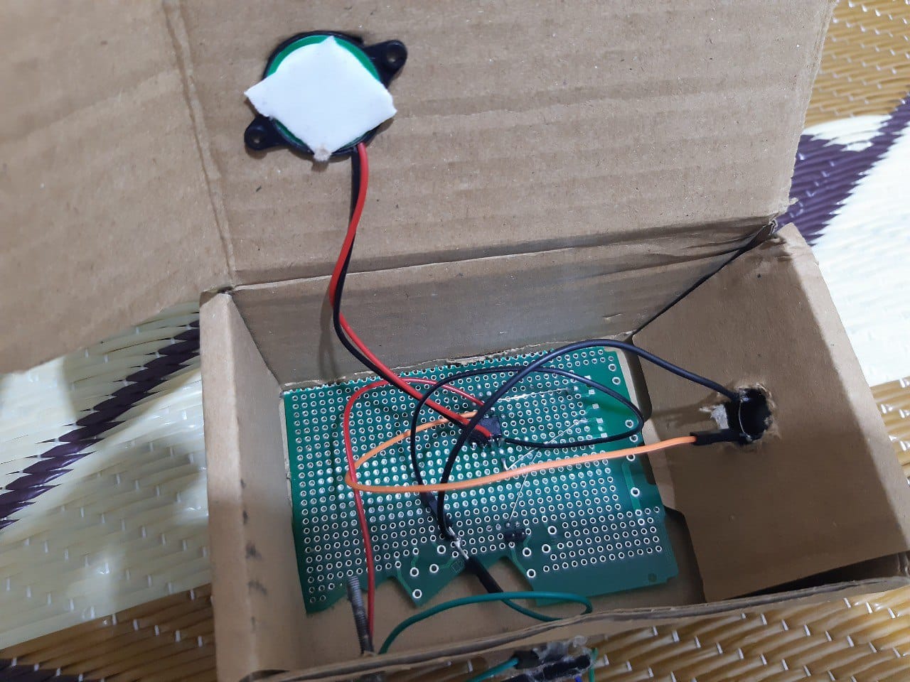
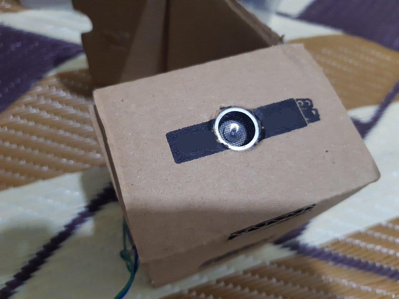
I built this simple circuit and used it alongside my ultrasonic repellent. As seen in the demo video, although the ultrasonic signals are inaudible to the human ear, they become clearly detectable through the bat detector’s buzzer. This allowed me to verify both that the repellent was working and to estimate its operational range
Gallery
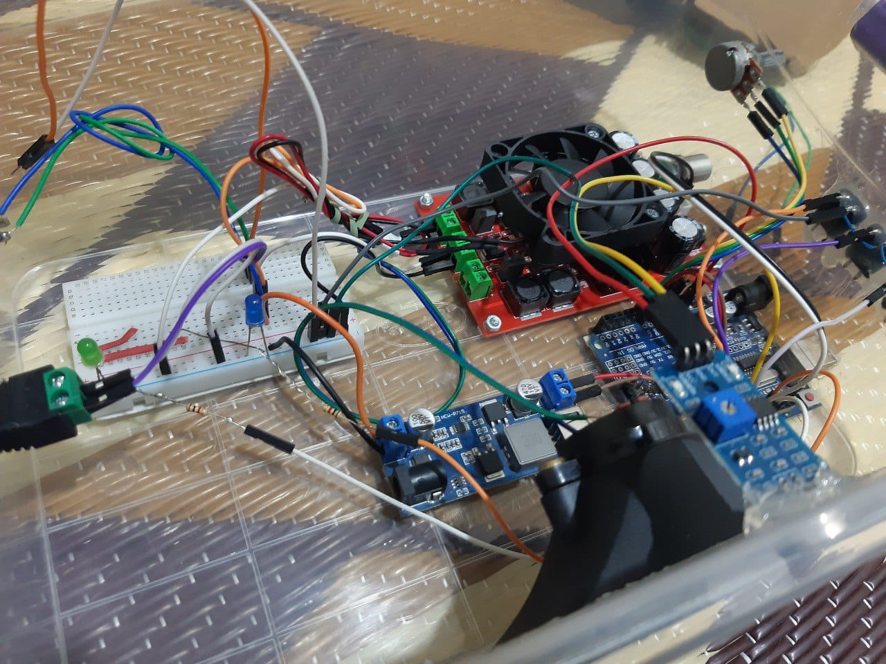
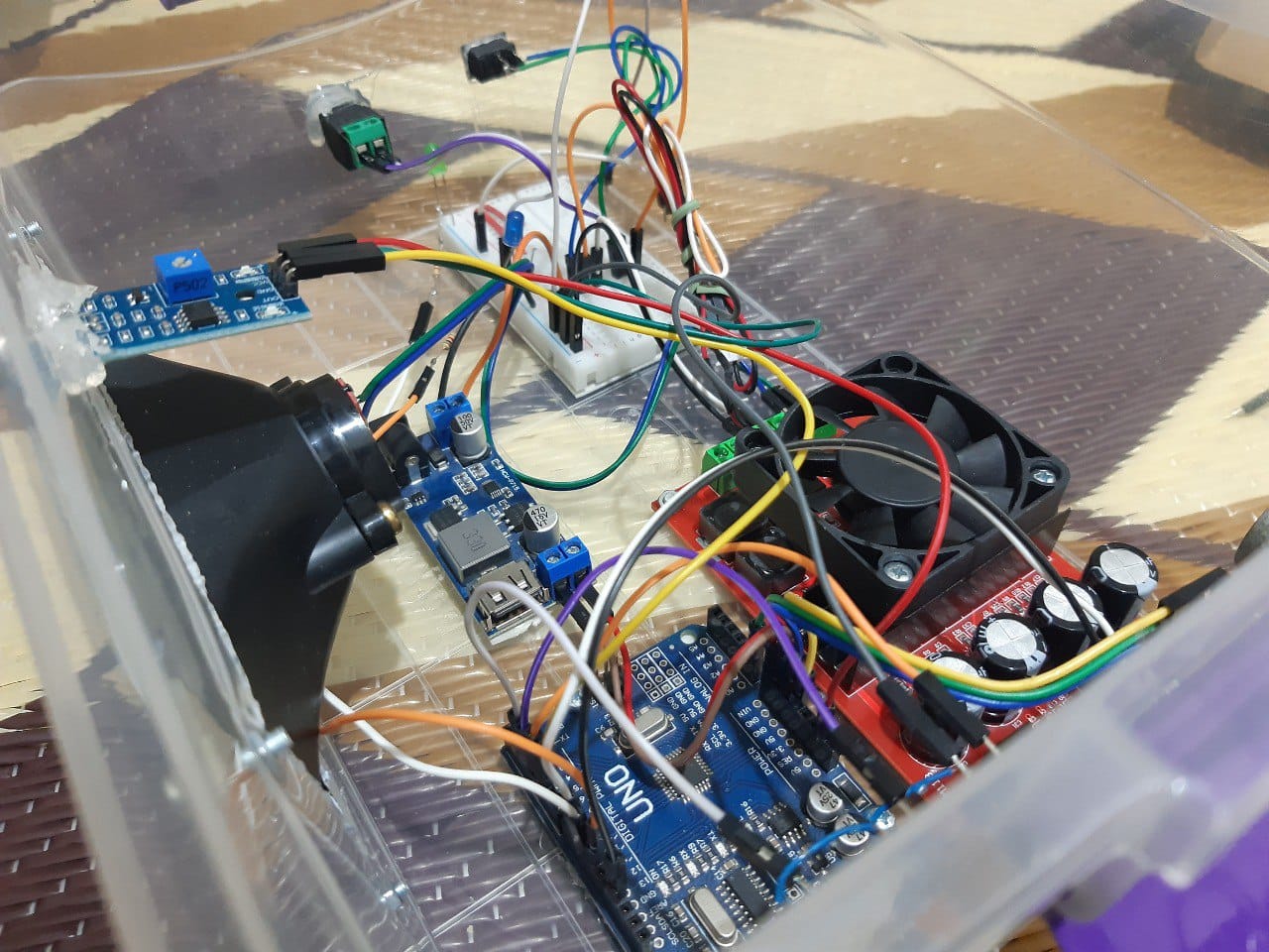
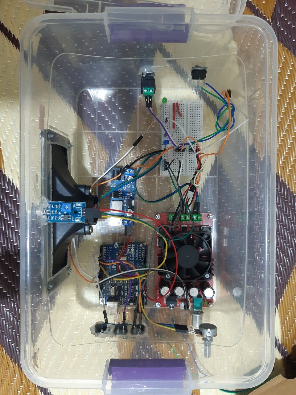
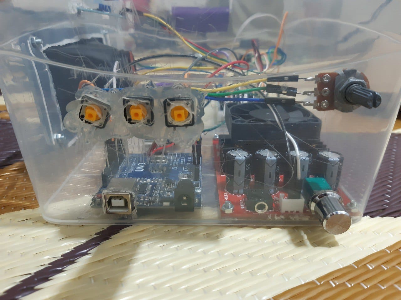
Demo Video
Summary
When activated, the device emits ultrasonic signals that dogs can hear clearly. At first, they will run away immediately. However, over time dogs may begin to tolerate the sound if they realize it poses no real threat.
To maintain effectiveness, it is recommended to combine the ultrasonic signal with another deterrent (such as throwing small stones or making sudden movements) at least a few times. Eventually, dogs will associate the ultrasonic sound with danger and flee immediately upon hearing it.
The device was tested successfully and works as expected. Unfortunately, I was unable to test it extensively on stray dogs because, shortly after completing the device, the local municipality removed all stray dogs from my area.